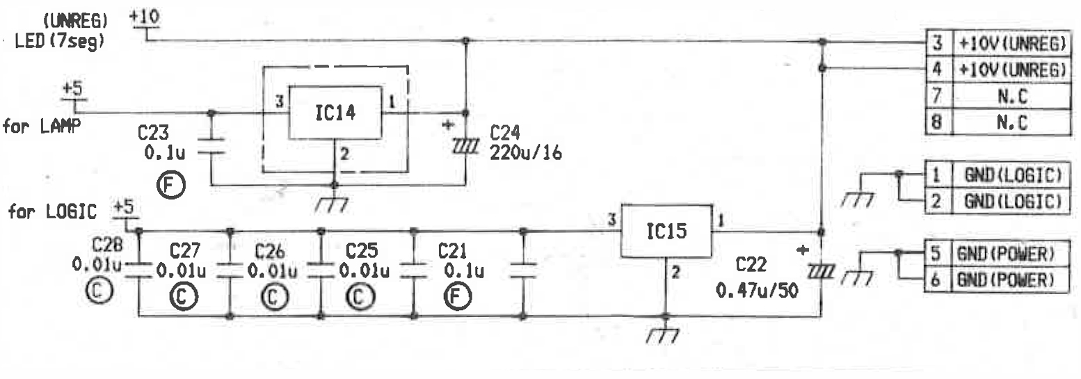
The MTR-12 provides the auto-locator with an unregulated 10V DC supply on two different pins of the connector. The auto-locator uses that supply to directly drive the LED digit displays for both Tape Time and Locate Time. It also splits off of that line to two, separately regulated and filtered, 5V DC lines for use with the logic circuit and the lamps.
Since I am not going to be having any hardware displays or lights, all I really need to power is the Arduino microcontroller. Once it has power, I can make it supply 5V to any external logic that I may end up needing for the rest of the project.
I originally thought I would have to build something to provide a regulated supply for the Arduino, but it turns out that I don’t. The Arduino is normally powered from the USB port, or from an external supply through the power jack. But, it also has a Vin pin. The requirement for this pin (or the power jack for that matter,) is for something between 7V and 12V DC which it will then regulate to 5V for itself and any peripherals. It couldn’t be more perfectly suited to the 10V supply from the tape machine. All I should need to do is run a wire from one of the GND (POWER) pins (18 or 21) to the GND on the Arduino, and another from one of the +10V (UNREG) pins (19 or 20) to the Vin on the Arduino, and the unit should power up.
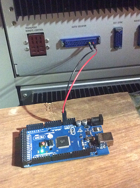
Yep… All good. Power up has been achieved. That was easy. Lol. With any luck, the rest of this project will go as smoothly as this did… 🙂
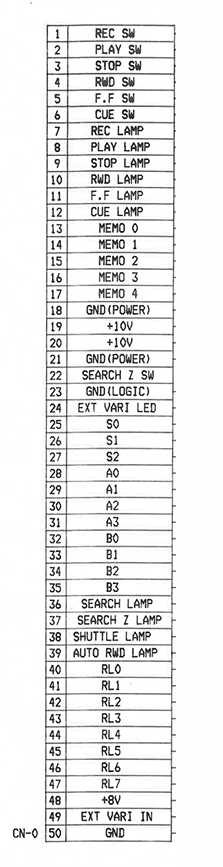
P.S. I know that the pin numbers on the power supply schematic don’t match what I just said, but those are a reference to an internal connector within the auto-locator. Here is the pin-out for the main connector from the tape machine. Whenever I reference a pin number, it will be on this connector.