In my quest for digital control of our analogue mastering facility, I have been looking at the reel to reel machines. I would like to be able to fully control the 1/4″ machine (Otari MTR-12) from the computer. I could make a simple remote for it, but how boring would that be? An auto-locator would be much better, but they are rare nowadays, and wouldn’t do exactly what I have in my head anyway. So, the big question is:
Could one make an Arduino microcontroller act as a midi-controlled auto-locator for an Otari MTR-12?
After some careful analysis of the schematic for the old auto-locator offered by Otari, I can’t see any reason why one couldn’t.
The brains for this functionality are actually in the tape machine, and the auto-locator is really just some switches and digital display elements. The timing for the digital circuit may be the only challenging aspect of the project, as I would like the tape and locate times to be reported properly and instantly, of course.
So, I will dive into it and report my progress. Should be fun and interesting. Feel free to make fun of me.
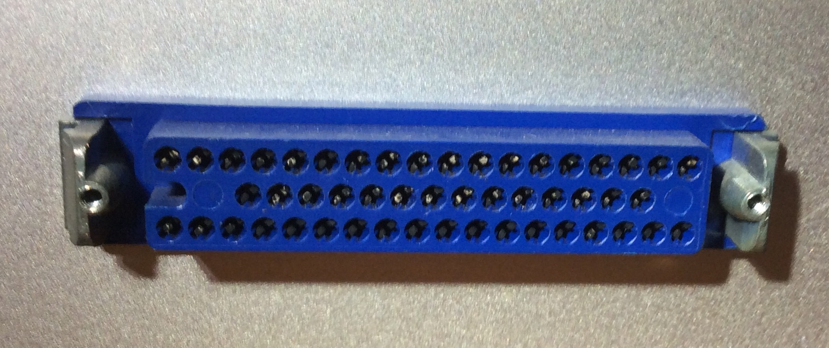
The jack for the auto-locator is a rectangular, keyed, 50 pin, 3 row (18/14/18) connector that does not seem to exist any more. It is a little under 2 inches (5 cm) in the long dimension. The internet seems to have no idea who made these, or if you can get a male version to mate with it. Even the old, crusty guys that hide from humans in the back of the electronics supply place had absolutely no idea who manufactured this. So, I will have to make the male one if this works out and I get a functioning unit. For now, and only for proof of concept, I will make do with whatever I can figure out. If anyone knows anything about this type of connector, please do enlighten us.
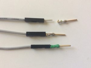
I went and purchased a 100 pack of D-Sub pins ($6,) and have assembled some test wiring. The D-Sub pins are needed, as the jumper wires are meant for breadboards, and the pins on them are a little too small to be gripped by the connector’s receptacles for a good, solid connection. I have now soldered a bunch of them to the ends of the jumper wires. They will eventually be tightly packed together on the connector too, so a bit of heat-shrink will go a long way under those conditions.
So, we are ready to go with proof of concept. Stay tuned.
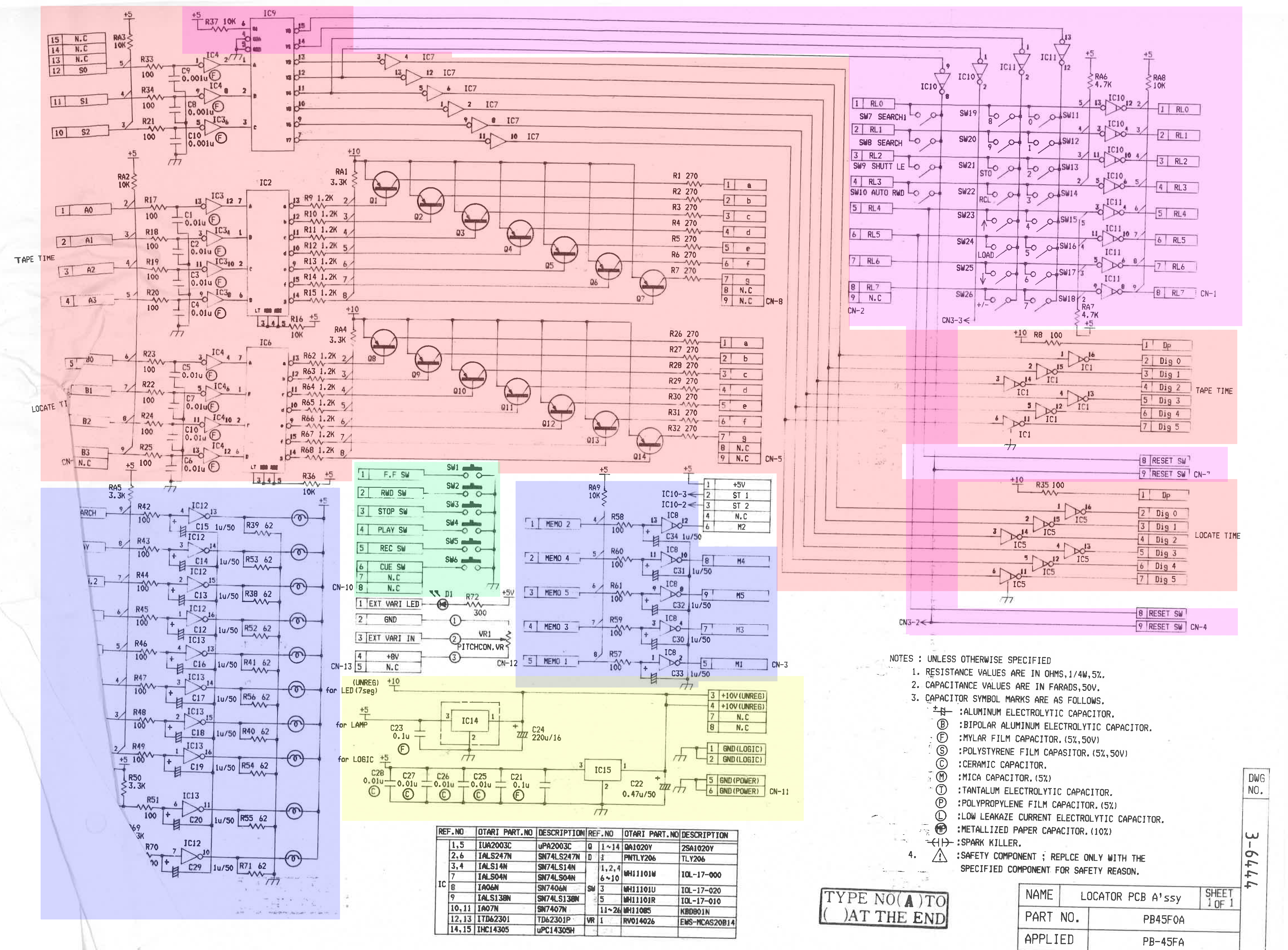
Here is a marked-up schematic for the old auto-locator that was made for the MTR-12 back in the day.
I’m going to split this project into the following tasks:
Power (yellow)
Lamps (blue)
Switches (green)
Display (orange)
Keypad (purple)
And then add the things that aren’t part of the original:
Midi Functionality
Control Software
I don’t plan on incorporating the variable speed control into my version of this, but one certainly could. I would simply add a digital potentiometer to the Arduino. I have no use for that functionality, as we are a mastering facility, and I can’t remember the last time someone asked me to change the playback speed of a tape machine.
So, here we go. First up will be the power section…
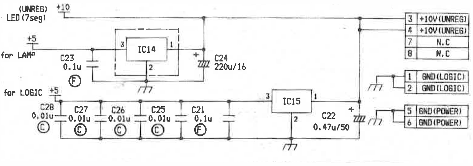
The MTR-12 provides the auto-locator with an unregulated 10V DC supply on two different pins of the connector. The auto-locator uses that supply to directly drive the LED digit displays for both Tape Time and Locate Time. It also splits off of that line to two, separately regulated and filtered, 5V DC lines for use with the logic circuit and the lamps.
Since I am not going to be having any hardware displays or lights, all I really need to power is the Arduino microcontroller. Once it has power, I can make it supply 5V to any external logic that I may end up needing for the rest of the project.
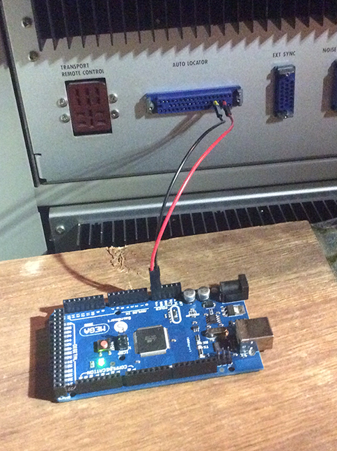
I originally thought I would have to build something to provide a regulated supply for the Arduino, but it turns out that I don’t. The Arduino is normally powered from the USB port, or from an external supply through the power jack. But, it also has a Vin pin. The requirement for this pin (or the power jack for that matter,) is for something between 7V and 12V DC which it will then regulate to 5V for itself and any peripherals. It couldn’t be more perfectly suited to the 10V supply from the tape machine. All I should need to do is run a wire from one of the GND (POWER) pins (18 or 21) to the GND on the Arduino, and another from one of the +10V (UNREG) pins (19 or 20) to the Vin on the Arduino, and the unit should power up.
Power up…
Yep… All good. Power up has been achieved. That was easy. Lol. With any luck, the rest of this project will go as smoothly as this did… 🙂
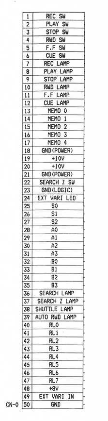
P.S. I know that the pin numbers on the power supply schematic don’t match what I just said, but those are a reference to an internal connector within the auto-locator. Here is the pin-out for the main connector from the tape machine. Whenever I reference a pin number, it will be on this connector.
The lamp section of this is going to be quite simple as well, although there are a couple of parts to it.
The Otari has pins for all ten of the lamps that would normally be on the auto-locator, as well as five extra that it calls MEMO (0 through 4.) The standard lamps are Rec, Play, Stop, Rew, F.F, Cue, Search, Search Zero, Shuttle and Auto-rewind. The MEMO lamps are used to indicate something has been stored in one of the 5 memory locations that the auto-locator could store. I am not going to use these, as I plan to store my locations on the computer.
These lamp outputs seem to conform to regular digital voltages, so a LOW signal (or 0) is a voltage between 0V and 1.5V, and a HIGH signal (or 1) is between 3.5V and 5V. To simplify, if the Rec pin has a voltage over 3.5V, the Rec lamp is on. If not, and it is under 1.5V, it’s off. This should work fine with what the Arduino expects to see.
The Hookup:
I am going to use the analogue inputs on the Arduino, as I want to keep the other inputs free for the display, switch and keypad parts of this project. The analogue inputs can act as either analogue or digital inputs. I will be configuring them as digital inputs. The wiring is straight forward:
REC Lamp (pin 7) -> Input A0
PLAY Lamp (pin 8) -> Input A1
STOP Lamp (pin 9) -> Input A2
RWD Lamp (pin 10) -> Input A3
F.F Lamp (pin 11) -> Input A4
CUE Lamp (pin 12) -> Input A5
SEARCH Lamp (pin 36) -> Input A6
SEARCHZ Lamp (pin 37) -> Input A7
SHUTTLE Lamp (pin 38) -> Input A8
AUTO RWD Lamp (pin 39) -> Input A9
The Arduino Code:
The Arduino uses a version of the C programming language, and I am quite comfortable in C, so this should be easy.
I have written two functions: getLamps() and sendLamps(). These interact with two variables, currentLamps and lastLamps, which are both 16 bit integers. I need them as 16 bit numbers, because I am going to use one bit per lamp, and there are ten lamps, so an eight bit number isn’t large enough to hold them. Why am I squishing all of the lamps into one number? Well, I am thinking ahead to where the bottle-neck will be. The slowest thing in this project is definitely the MIDI communication, and I want to keep the messages as small as possible. When the Arduino sends the lamps to the computer, it will only have to send a few bytes, making it super fast.
This is how I will use the bits. They will be assigned like this:
Bit 9
Bit 8
Bit 7
Bit 6
Bit 5
Bit 4
Bit 3
Bit 2
Bit 1
Bit 0
AUTOREW
SHUTTLE
SEARCHZ
SEARCH
CUE
F.F
RWD
STOP
PLAY
REC
If a lamp is on, the corresponding bit will be set (made to be a one.) If it is off, the corresponding bit will be cleared (set to zero.) For example, let’s say the MTR-12 is in record. It should have the record lamp and the play lamp on. That condition should set my currentLamps variable to be binary 0000000011. If I then hit the stop button, the stop lamp comes on, while the play and record lamps go off. This should set my currentLamps variable to be binary 0000000100.
The Arduino has two standard, required functions: setup() and loop(). The setup() function is run when the unit first powers up, and then it enters the loop function and runs that until the power is shut off.
This will open up the serial connection, so I am able to send myself messages, and then it calls the sendLamps() function to show me the currentLamps variable. This is really only for testing the concept, although I will simply rewrite the sendLamps() routine to send a midi message later on. The message that I should see when this setup() function runs is just a zero, as the currentLamps variable is set to zero on power up, which means ‘All Lights Off.’
The program then enters the loop() function.
void loop() { getLamps(); }
The getLamps() function reads all of the lamp pins and, if a pin is HIGH, it sets the correct bit in the currentLamps variable. If it isn’t HIGH, it clears the bit.
It then compares the currentLamps variable to the lastLamps variable. If currentLamps is the same as lastLamps, it doesn’t do anything. If it is different, the lamps have changed since the last time the program sent a message, so it will then send a message with the new lamps. Then it goes back into the loop() function and does it all over again.
And that’s it. Now for some testing…
Testing:
If you have made it this far, you might want to make this video full screen, so you can see what the display is showing. Taken with my iPad, so the quality isn’t that great, and the focus isn’t super stable…
Conclusions:
Works like a charm. Response is very fast too.
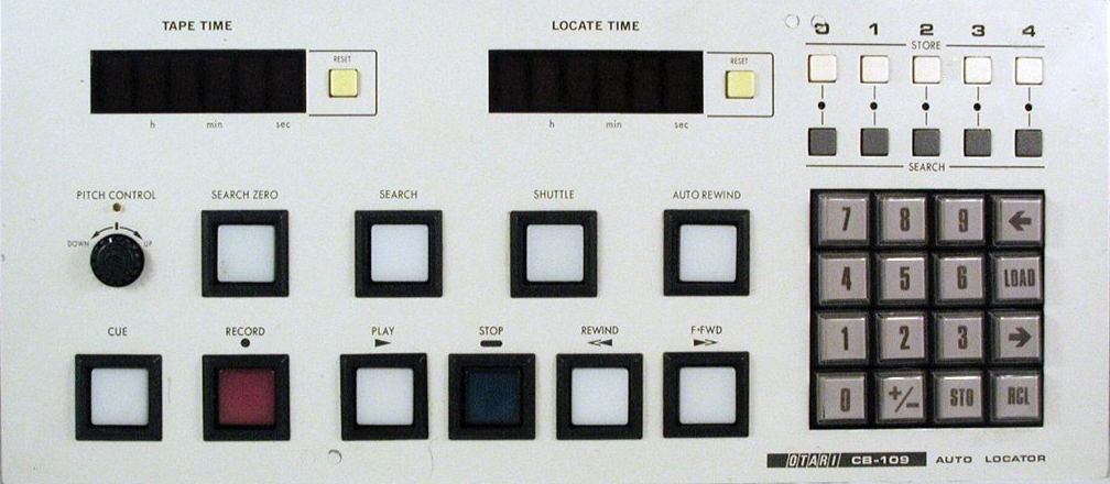
Note to self: The last thing I do in the video, at the point where you lose sight of the buttons, is hit the search zero button on the other side of the machine. The button on the MTR-12 does not seem to trigger the searchZ lamp to come on. I am assuming that it will once I start triggering a search zero from (what would be) the auto-locator. The button on the machine is not a standard lamp button, but the button on the auto-locator, as you can see here, was.
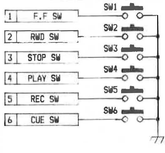
The switching circuit for the auto-locator is a very simple circuit. The MTR-12 sends out a voltage on a separate pin for each switch and, if any of these are shorted to GND, that switch is considered to be pressed.
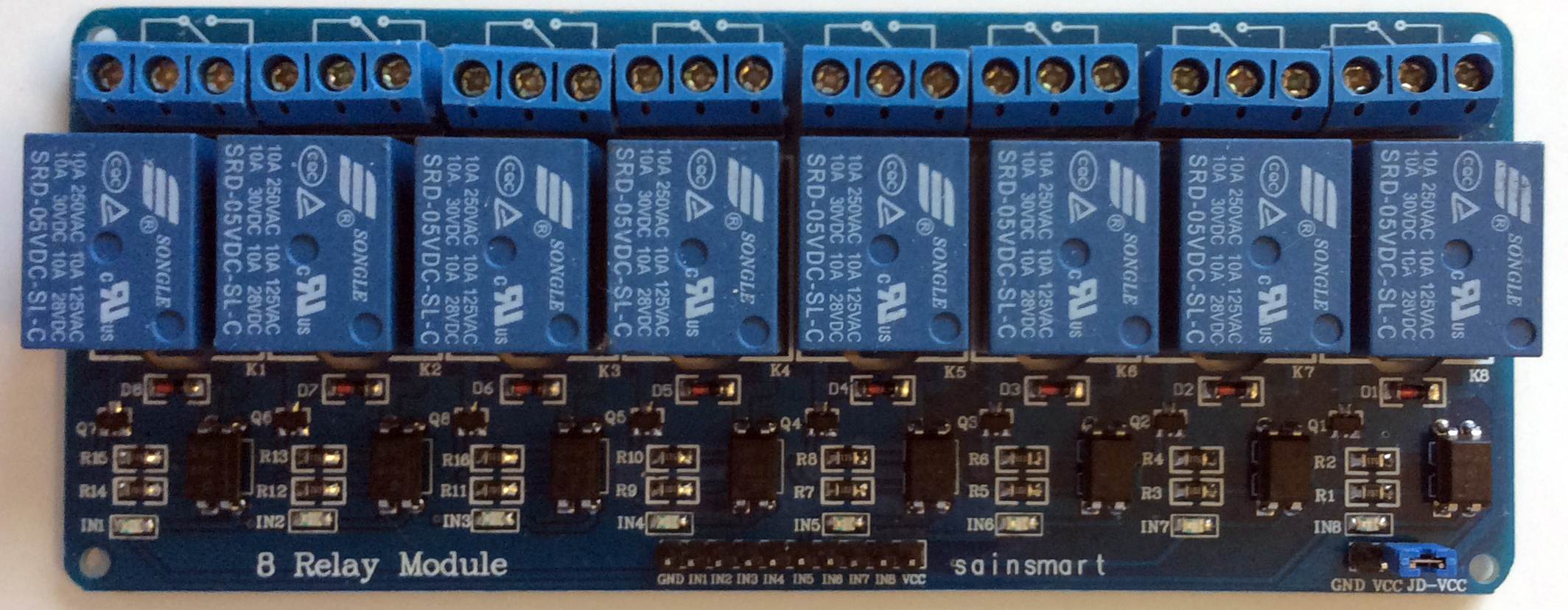
The Arduino can’t really do this, so I purchased an 8 relay module from here.
Relay module.
This module is designed to work with the Arduino (or any other microcontroller) and… it was only $10.49, which appealled to my cheapness immensely. 🙂
The relays work like this: Each relay has three pins. If the relay is off, pins 1 and 2 are connected together, if it is on, pins 2 and 3 are connected together.
My plan is that I am going to connect all of the #2 pins together, and then connect them to GND. There is (happily) a spare GND pin on the relay module that I can use. It is meant for the little configuration jumper in the bottom right hand corner of the board, but it will serve my purposes well, and appears to be unused in the default configuration. Documentation on this module is pretty thin, and I can’t get a clear idea as to what the configuration jumper is for. I think it must change the relays from being on when the control line is LOW to being on when it is HIGH, but this is just a guess.
Relay Module Grounding Scheme
With the #2 pins all connected to ground, I will then connect the switch outputs from the MTR-12 to the #3 pins of the relays. It will be connected like this:
Record Switch (Pin 1) -> Relay 1 (Pin 3)
Play Switch (Pin 2) -> Relay 2 (Pin 3)
Stop Switch (Pin 3) -> Relay 3 (Pin 3)
Rewind Switch (Pin 4) -> Relay 4 (Pin 3)
Fast Forward Switch (Pin 5) -> Relay 5 (Pin 3)
Cue Switch (Pin 6) -> Relay 6 (Pin 3)
Search Zero Switch (Pin 22) -> Relay 7 (Pin 3)
The first six were all of the switches in the CB-109 auto-locator. There was, however, another remote that was available for the MTR-12, the CB-111, and it used the same port. It was a very simple remote control, with no bells and whistles, but it did have a Search Zero switch that it needed an output for. I have decided to wire that up for this test, even though the CB-109 had that functionality moved into the keypad section, and didn’t use the searchZ switch output. More on that later. I have an extra couple of relays on this module anyway, so I may as well use this opportunity to see if the SearchZ Lamp comes on when I trigger it.
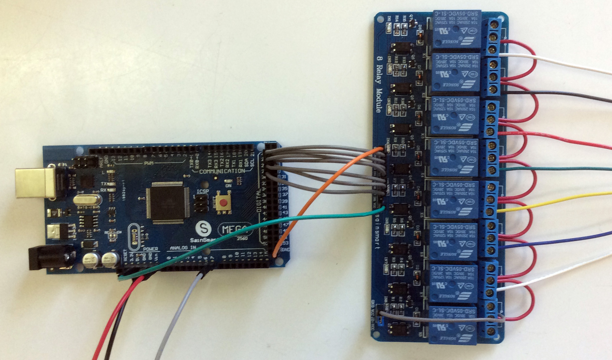
The connections between the Arduino and the Relay module as are follows:
GND -> GND
5V -> Vcc (Power supply)
D22 -> In 1 (Controls relay 1. LOW=On, HIGH=Off)
D23 -> In 2 (Controls relay 2)
D24 -> In 3 (Controls relay 3)
D25 -> In 4 (Controls relay 4)
D26 -> In 5 (Controls relay 5)
D27 -> In 6 (Controls relay 6)
D28 -> In 7 (Controls relay 7)
When I want a switch to be activated, all I will have to do is change the state of that digital output to LOW. To deactivate it, I simply change the state to HIGH. The switches will be:
D22 Record
D23 Play
D24 Stop
D25 Rwd
D26 F.F
D27 Cue
D28 SearchZ
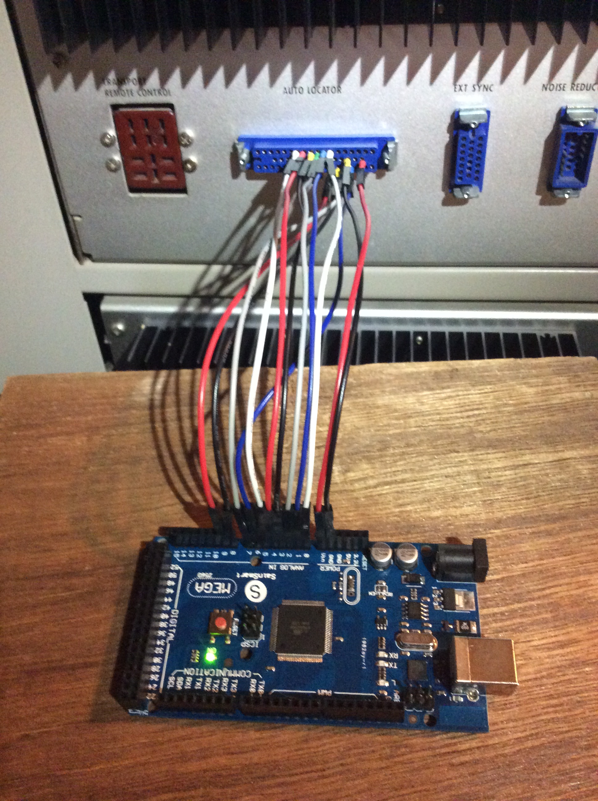
The whole thing wired together looks like this. I have removed the previous lamp wiring (except for the searchZ lamp) for clarity.
Arduino to Relay Module Wiring
Tomorrow, I will hook it up to the MTR-12, write the code for the Arduino, and then do some testing.
This morning I hooked the whole thing up to the MTR-12, wrote the software, and did some testing.
Software:
For the test software, I added a couple of routines to the lamps program. First, I added the processCommands() routine to accept commands through the serial(USB) port. I wanted to be able to send it a switch number, and have the unit turn that relay on for a brief period of time. As brief as possible. It also has to tell me that the switch has been turned on, so I know what is going on. This routine is only for testing the functionality. I also added the setSwitches() routine to turn the switches on (and off.) This routine also let’s me know when a switch has been turned off.
I have made an array of integers called switches[] and set them all to be zero. If the processCommands() routine receives a number, it changes the appropriate switches[] element to be 500. Every time the Arduino goes through a loop, it calls the setSwitches() routine and, if any of the switches are not zero, it pulls the appropriate relay module pin LOW, thereby activating the relay, and the switches[] element is decremented. Once the switches() element reaches zero, the appropriate pin is pulled HIGH again. This will allow me to see how long the switch needs to stay on in order to trigger the action. 500 loops should be a good starting point.
void loop() { setSwitches(); getLamps(); if (Serial.available()>0){processCommands();} }
Testing:
Works great. The video tests all of the switches, except the CUE switch, as that one needs to be held down for the function to be apparent, and I haven’t written a routine for that. This is just proof of concept, remember. I did test that switch, and it does fire, so all is well.
Conclusions:
Well, the first thing you may notice is, when I hit switch 7 (search zero,) the damn lamp still doesn’t come on. Not sure if maybe our machine has a problem in this regard, or if it will fire when I trigger it properly from the fake keypad routine that will be written later on. This was a bit of a shock for me, as I fully expected it to send a searchZ lamp on message.
After I shot this, I fooled around reducing the time that the switches stayed on. When I went down to 75 loops, the MTR-12 stopped responding to the commands, so I increased it to 100 and everything works well. 100 loops on the Arduino is a really short period of time. As I add more functionality to the loop() routine, it will extend the time it takes for each loop to execute, so I should be able to pull that number down in the future versions.
With the lamps and switches working, I will now move on to the more tricky stuff, starting with the time displays. It may take a few days to make progress on this. Stay tuned…
This will be eventually be a complete list of parts for this project, as I will add to it as I discover that I need them.
Arduino Mega 2560 Rev. 3 – $38.50 on the Arduino site, but I bought one of these for $19.99, because I am a cheap bastard. Arduino already have a bunch of my money, so I don’t feel bad about buying a knockoff for this project.
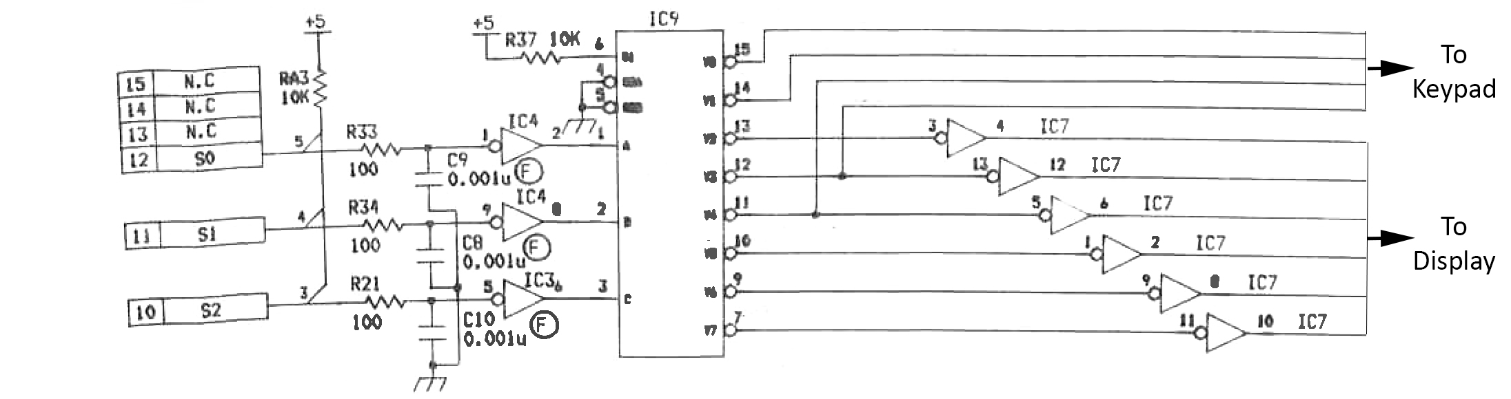
The ‘S’ channel (lines S0, S1 and S2) is the main digital control channel for the auto-locator. It controls the timing for both the displays and the keypad. It is so important to the way the system functions, I am going to say that the ‘S’ must stand for ‘Supreme Commander.’
Warning: we are about to get into some digital truth tables, so brace yourselves…
The resistors and capacitors on the three lines serve as spark protection and pull up for the digital lines. The pull up is there to force the lines to go into a HIGH state if nothing is connected to them (floating inputs.) We will just ignore that stuff for now. I assume, maybe unwisely, that the processor on the Arduino has some form of spark protection anyway.
The lines then hit IC 3 and 4, which are SN74LS14N chips. These are Hex Schmitt-Trigger Inverters. That means that they clean up the signal coming in and make it consistent. It also means that they flip the logic coming in.
S Input     Inverter Output
HIGH        LOW
LOW         HIGH
Then the lines go into IC 9, which is an SN74LS138N. This is a 3 line to 8 line decoder. If we think of a HIGH state as a 1, and a LOW state as a 0, this is what happens with the outputs of the decoder:
S Input
Inverter Output
Decoder Output
S2
S1
S0
S2
S1
S0
0
1
2
3
4
5
6
7
1
1
1
0
0
0
0
1
1
1
1
1
1
1
1
1
0
0
0
1
1
0
1
1
1
1
1
1
1
0
1
0
1
0
1
1
0
1
1
1
1
1
1
0
0
0
1
1
1
1
1
0
1
1
1
1
0
1
1
1
0
0
1
1
1
1
0
1
1
1
0
1
0
1
0
1
1
1
1
1
1
0
1
1
0
0
1
1
1
0
1
1
1
1
1
1
0
1
0
0
0
1
1
1
1
1
1
1
1
1
1
0
These decoder outputs are used to activate whichever part of the displays and keypad that the MTR-12 wants to send information to, or get information from. Each output activates a single thing, except for outputs 3 and 4, which activate a digit in the display and a part of the keypad at the same time. Here is what that looks like.
S Input
Inverter Output
Decoder Output
Activates
S2
S1
S0
S2
S1
S0
0
1
2
3
4
5
6
7
1
1
1
0
0
0
0
1
1
1
1
1
1
1
Keypad
1
1
0
0
0
1
1
0
1
1
1
1
1
1
Keypad
1
0
1
0
1
0
1
1
0
1
1
1
1
1
Sign Digit
1
0
0
0
1
1
1
1
1
0
1
1
1
1
Hour Digit (and Keypad)
0
1
1
1
0
0
1
1
1
1
0
1
1
1
Ten Minute Digit (and Keypad)
0
1
0
1
0
1
1
1
1
1
1
0
1
1
Minute Digit
0
0
1
1
1
0
1
1
1
1
1
1
0
1
Ten Second Digit
0
0
0
1
1
1
1
1
1
1
1
1
1
0
Second Digit
I will be dealing with the keypad at a different time, so only the digit activation parts are of interest to me at this point. If I remove all of the stuff between the inputs and what it is they activate, this is what I end up with:
S Input
Activates
S2
S1
S0
1
1
1
—
1
1
0
—
1
0
1
Sign Digit
1
0
0
Hour Digit
0
1
1
Ten Minute Digit
0
1
0
Minute Digit
0
0
1
Ten Second Digit
0
0
0
Second Digit
I have a strong feeling that the S channel will just be continuously scrolling backwards through all 8 possibilities from 7 to 0, or in binary 111 to 000, and then starting over again. This should give us a forward scrolling in the decoder outputs. I should be able to see it doing this with a little Arduino code. It will be doing this very quickly, but that shouldn’t be a problem for the Arduino. The MTR-12 is older technology, and I would be very surprised if it is changing the S channel faster than, say, 10 kHz. The Arduino runs at 16 MHz, so it should be able to make some toast and have a little nap between the cycles of the MTR-12.
When the S channel changes, I want the Arduino to drop whatever it is doing and respond to the change immediately. The best way to do this is to assign a change in the S channel to an interrupt on the Arduino. If I look at the table above, it becomes apparent that, if I am correct about the scrolling, the line that will change every time the MTR-12 moves to the next number is the S0 line. I want to keep things as lean and simple as possible, so I will just attach the S0 line to a hardware interrupt on the Arduino. I will do this by using Digital pin 2 for that line, because it is one of the pins that can do a hardware interrupt, and adding the following code to the setup() routine:
This says to the Arduino every time the S0 line changes state, call the decodeS() function, which I will add to make sense of the three lines on the S channel and show me the result.
There is nothing in the loop, because I only want it to do something when the S0 line changes. I am going to create an integer variable called currentS. When the line changes, the decodeS() routine will read all three S lines and store the decoded result into this currentS variable. It will then show me the currentS variable through the serial port. Think of the currentS variable as which decoder output is activated.
Testing:
Perfect. Exactly as predicted. Tomorrow, I will move on to doing something useful with this information.