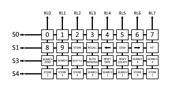
Sorry this took a few days, but I didn’t have a lot of free time to decipher the schematic. I had to go through the schematic and redraw the matrix for the keypad, as it was all very convoluted, spread over a couple of pages, and kind of hard to understand. The above image is actually what the keypad on the auto-locator schematic should look like. It is much clearer now. Since I am not going to have a physical keypad, I will figure out a way to fake having one with the Arduino, thereby (hopefully) getting the functionality of the keypad that can be triggered from MIDI.
The way the keypad seems to have worked is relatively simple. It used the lines decoded from the S Channel so that, when the S value was 0, 1, 3 or 4, those lines were sent to the keypad matrix (S0-S4 in the above image.) The MTR-12 has 8 inputs from the auto-locator (RL0-RL7,) which are the outputs from the keypad matrix. If a button on the matrix was pressed, it would pull whichever output it was connected to LOW during that currentS cycle. For example, let’s say I wanted to simulate the pressing of the ‘8’ key. In the above picture, you can see that I would need to pull RL0 LOW whenever the currentS was equal to 1. If I wanted to simulate a pressing of the Tape Time Reset button, I would pull the RL4 line LOW on every currentS cycle that is equal to 3. I’m not sure why they decided on 0, 1, 3 and 4. That seems odd to me.
Without going into too much detail about the electronic challenges of this circuit, these outputs may be a bit challenging for me. The original auto-locator circuit used SN7407N chips to buffer and drive these outputs to the MTR-12. These chips do several things, one of which is to convert logic levels between TTL and MOS. This isn’t an issue for me, as the Arduino is a CMOS chip. The SN7407N chips are also high sink-current drivers, and I am not sure if the Arduino has enough jam for this. The digital pins on the Arduino that have the best driving capabilities are 10, 11, 12, 13 and 50, 51, 52, 53, so I will be using those for testing this capability. I may end up having to put a couple of SN7407s in-between the Arduino and the MTR-12, which would be fine, as they are currently only $1.20 each at mouser. I have high hopes that I won’t need to do that though, as the Arduino is impressing me, and it has yet to disappoint me throughout this project.
I am going to treat the keypad like I did the switches. I will simulate a key press for the smallest amount of time required to activate the function. This will take a little experimentation, but I need these key presses to happen fast. That way, when the Arduino receives the message “go to 1 minute and 23 seconds,” it can enter the time into the locate in a way to make it seem like it is an almost instantaneous reaction to the command. That command probably requires five key presses, Locate Time Reset, 1, 2, 3 and Search, so the longer each key press takes, the slower the response will feel.
Before I do that, or even just test this rig out, I need to make a command interpreter that is capable of receiving a series of numbers, like the 123 in the above example, turn them into a series of key presses, which it will then execute in sequence, each one executed after the previous one has finished. This will take a bit of thought. Stay tuned.